Long before the observatory was completed, the telescope was ordered from RC Optical Systems due to its long delivery lead time (10 months).
Upon arrival of the telescope, it was installed in the observatory along with the mount and other equipment.
Fine tuning the equipment, computers and software took several months thereafter before the telescope was fully operational.
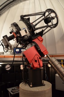
The telescope is a 16 inch Ritchey Chrétien manufactured by RC Optical Systems. The Ritchey optical design is a special type of Cassegrain telescope made to eliminate coma in order to provide a large field of view. The design has hyperbolic primary and secondary mirrors, and therefore, has no chromatic aberration or spectral dispersion.
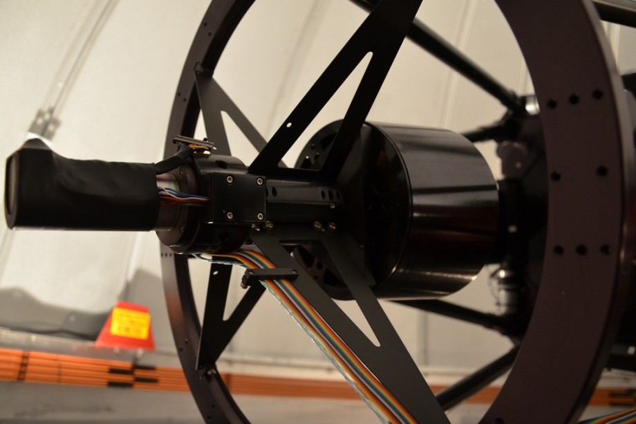
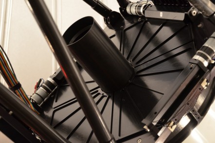
The telescope construction is an open tube truss. The truss support bars are made from carbon fiber to reduce any structural changes due to temperature fluctuations. The open truss design also helps reduce tube currents in the telescope and allows the telescope to adjust to ambient temperature sooner.
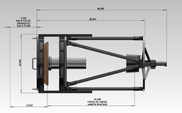
These elements also maintain focus stability over a wide temperature range. The telescope has a focal length of 3,649 mm, an f / ratio of 9.0 and a back focus distance of 9.29 inches. The diagram above indicates the telescope’s manufactured specifications.
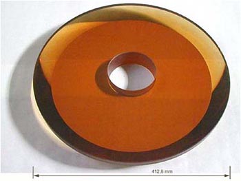
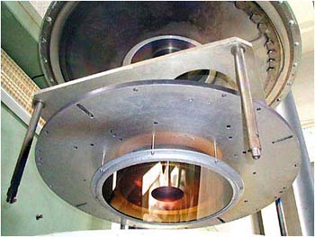
The telescope optics are ion milled using an ion beam to remove material and polish the mirror at the molecular level, resulting in optics that are guaranteed to be better than 1/40th wave RMS. An interferometric test and fringe analysis are provided with each set of optics. The picture above shows a mirror blank being polished with an ion beam.
Telescope Control Unit
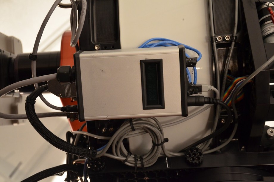
The telescope has an integrated control unit that interfaces with cooling fans, a heated secondary mirror to prevent dewing, a secondary focuser, integrated large format rotator and robotic mirror cover.
The cooling fans are controlled by a computer that monitors and adjusts the fan speed during the night to keep the primary mirror close to the ambient temperature. The secondary heater is also computer controlled to provide heat to the secondary so that it is slightly warmer than ambient to prevent dew from forming.
Secondary Focuser
The telescope is focused by moving the secondary mirror. The focuser is a zero image shift focuser with zero back-lash and a resolution of 1/40,000 of an inch.
The focuser is also computer controlled and can be monitored by computer to refocus the telescope automatically depending on temperature or filter changes.
Rotator
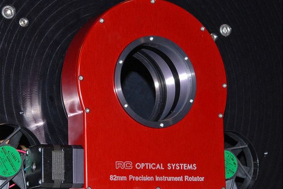
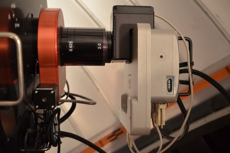
The rotator is attached to the back of the telescope and has an integrated field flattener to accommodate large format cameras and image sensors. The camera is attached to the rotator by extension tubes of a specific length to provide the correct back focus for the telescope to camera.
The rotator is used to rotate the entire camera assembly to a specific rotation angel in order to make it easier to locate a guide star on the camera’s integrated autoguider chip. The rotator is also under computer control and can be moved by the computer to locate and place a guide star on the autoguider chip without user intervention.
Robotic Mirror Cover
The telescope has an integrated robotic mirror cover composed of four overlapping flaps that open or close to expose or shield the primary mirror. This helps keep dust and insects off the primary mirror when it is not in use.
Because the design requirement is for robotic and remote imaging, the mirror cover can be open or closed remotely or under computer control.
Integrated Software Control
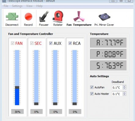
All of the various telescope control systems, fans, secondary heater, focuser and rotator are integrated and managed by the telescope control unit which is connected by ethernet to the observatory computer. Software running on the observatory computer interfaces with the telescope control unit so that all telescope subsystems can be controlled easily.
The software is ASCOM compatible which allows other software such as FocusMax to control focusing the telescope. The telescope control unit software interface is shown to the right.
The Mount
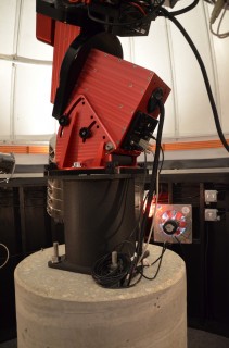 The telescope is mounted on a Bisque Paramount ME robotic mount. The Paramount was selected because it has sufficient capacity to carry the telescope and is tightly integrated with The SKY planetarium and control software. The paramount also has through the mount cabling which allows the power and control lines to run through the pier and also through the mount.
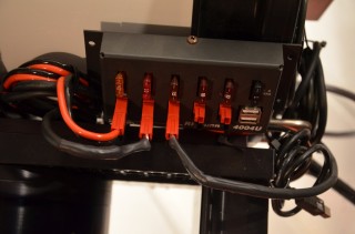 Power for the equipment mounted on the telescope is supplied though the mount to a 12 volt distribution panel called a RIGrunner made by Powerwerx. Providing power in this manner eliminates all power transformer “bricks” for each device and makes for a cleaner installation and less weight on the mount.
Camera, Autoguider and Adaptive Optics
The camera is an ST11000M manufactured by Santa Barbara Instruments Group (SBIG) and incorporates a class 1 chip and integrated autoguider and filter wheel. The filter wheel is loaded with LRGB and narrow band Gen 2 filter sets from Astrodon.
Specifications for the camera:
| Pixel Array | 4008 x 2745 |
| Total Pixels | 11 million |
| Pixel Size | 9 x 9 microns |
| Full well capacity | 50,000 e- |
| Dark Current | 1.5 e- /pixel/sec |
| A/D gain | 0.8e- / ADU |
| Read Noise | 11 e- RMS |
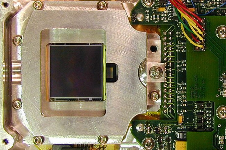
The integrated autoguider chip allows the camera to control the mount and the adapative optics unit to make sure the entire system accurately guides on a specific guide star. The picture to the right shows the interior of the camera.
The large chip in the center of the picture is the main imaging chip. The small chip to the right of the main imaging chip is the autoguider chip. The telescope field of view is oriented to place a “guide star” on the autoguider chip while the object to be imaged is placed on the main imaging chip. The camera then tracks the guide star to make sure it stays on the chip for accurate guiding over long exposures.
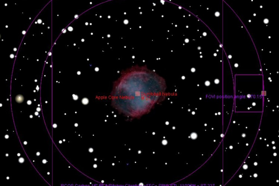
To place a guide star on the autoguider chip, the image may need to be rotated to find an appropriate guide star. This is the purpose of the rotator. The picture above shows the camera field of view indicator superimposed over the object to be imaged in the SKY X planetarium software. The field of view of the main imaging chip is represented by the large rectangle and the field of view of the autoguider chip is the much smaller rectangle to the right.
The Dumbell Nebula is centered on the main imaging chip. The autoguider chip can be rotated around the circle indicated by the field of view indicator. This is accomplished by picking an available guide star somewhere around the circle and commanding the rotator to move to that rotation position, which is called the “position angle.” The actual rotation and centering of the guide star is handled automatically by software on the observatory computer directing the rotator to move to the correct position.
Finally, an adaptive optics unit (AO-L) is also integrated into the camera equipment. The AO-L unit sits in front of the camera package to improve image quality, enhance stellar profiles and remove low order atmospheric effects. The AO-L incorporates a special piece of glass that is moved along an x and y axis by very precise electromechanical actuators that compensate for any movement in the guide star.
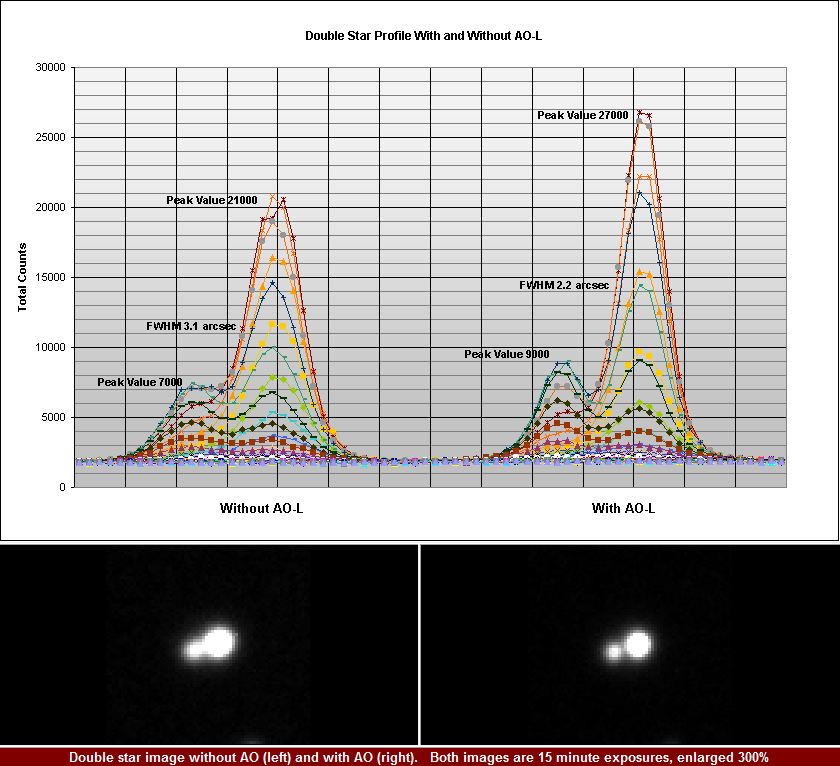
The AO-L unit allows high speed guiding at 5Hz to 10 Hz. The primary benefit of the AO-L unit is to improve stellar profiles and overall sharpness of the image. The comparison below (courtesy of SBIG) shows the improvement in stellar profiles by using the AO-L
Electroluminescent Panel
The observatory also uses an electroluminescent panel called a Flatman XL made by Alnitak Astrosystems. The panel provides an extremely “flat” or even source of illumination for taking flat frames which are used in calibrating images.
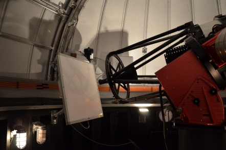
After a night of imaging, the telescope will automatically park in a certain position pointing at the Flatman panel. Once there, the observatory automation will activate the panel and the camera will proceed taking flat frames. The picture at right shows the telescope in its park position for taking flat frames.
